
 01
01AEROSPACEBUILT & FLIGHT-TESTED
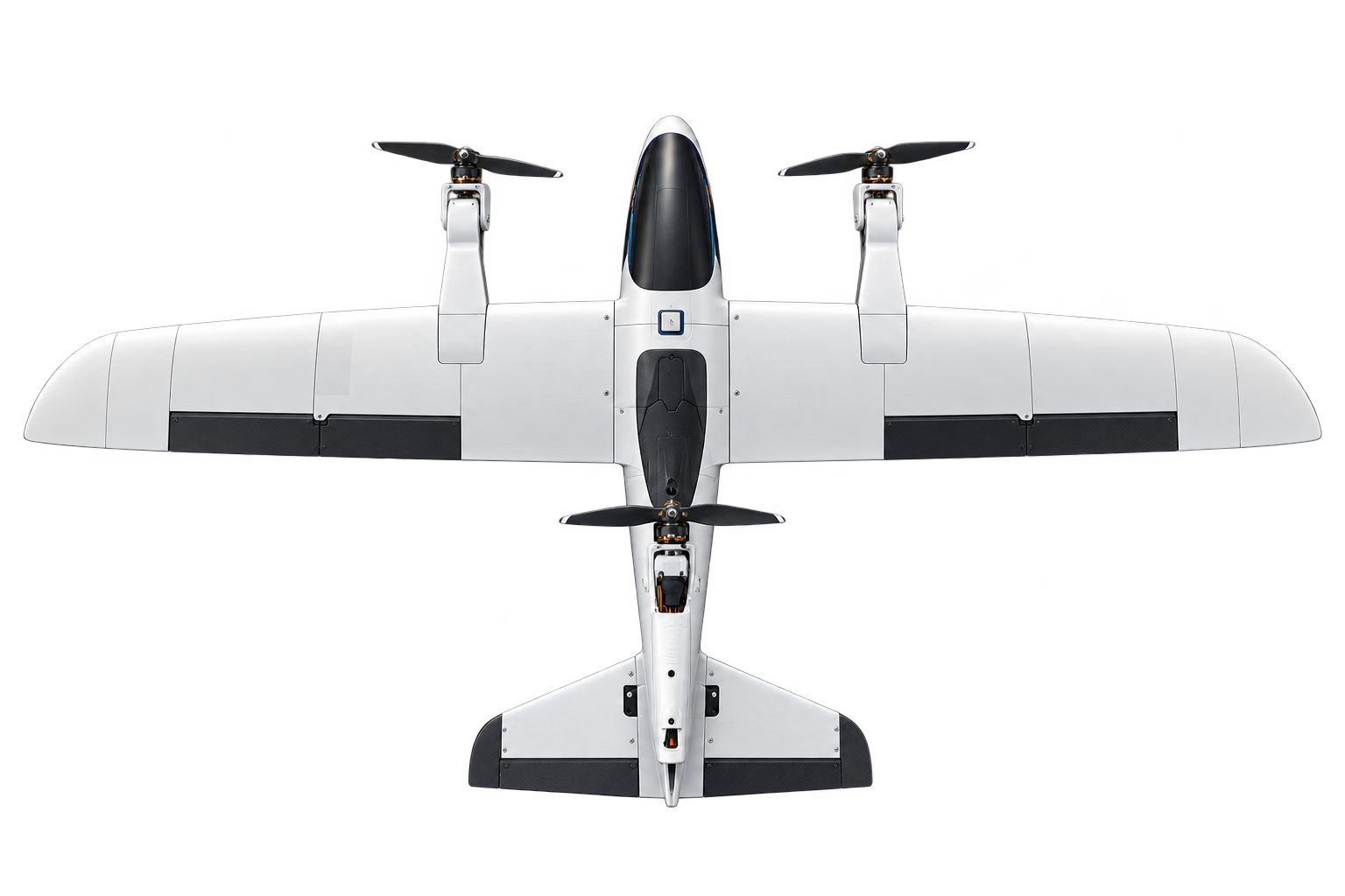
Vector V1 - Tri-rotor VTOL UAV
A fabricated and flight-tested electric UAV using three tilting propulsion units for vertical lift and transition to wing-borne forward flight.
MECHATRONICS / MACHINE DESIGN
A SolidWorks design for automated stamp sealing, combining roller-fed material handling with rack-and-pinion and linkage motion.
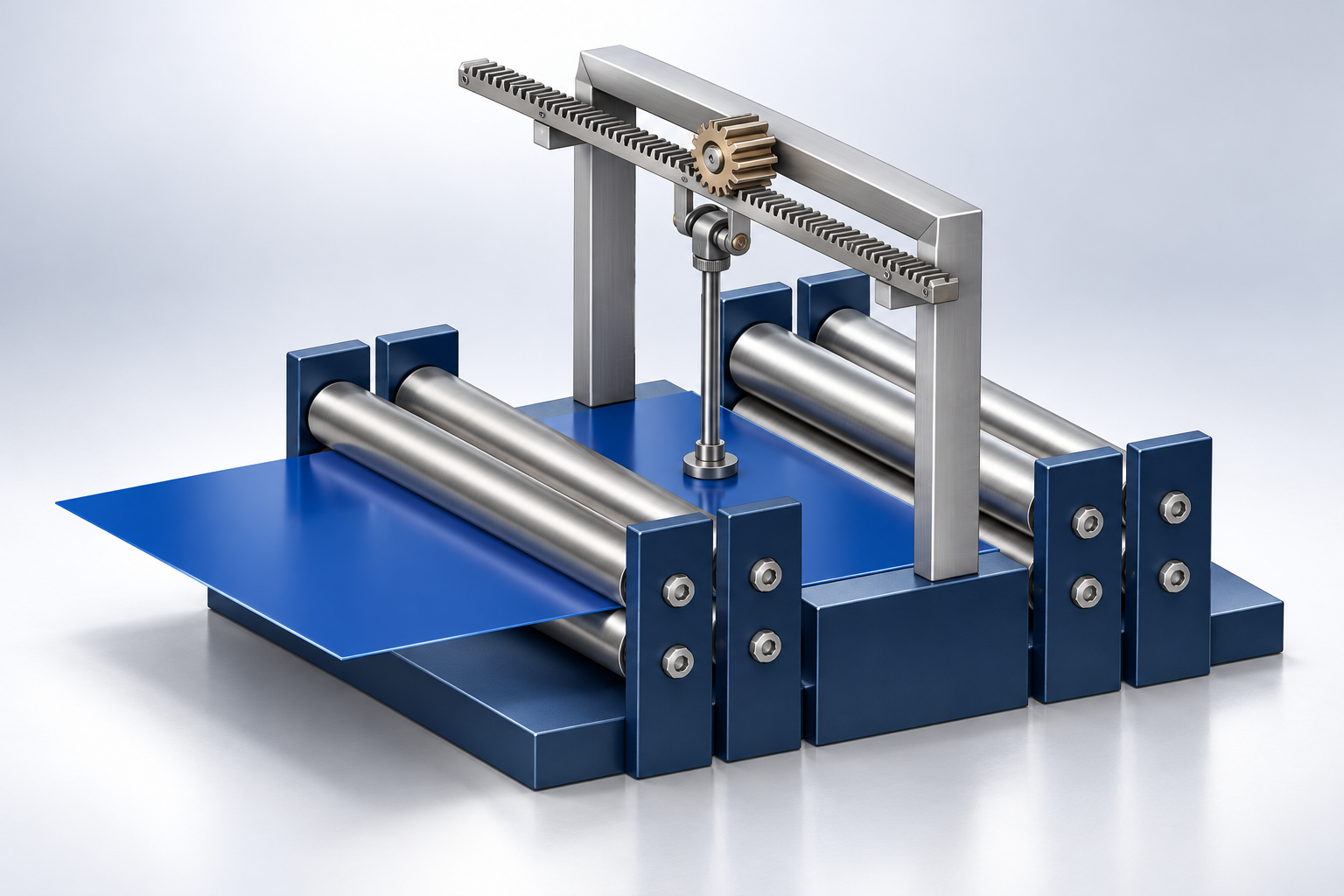
This project applies mechanical mechanisms to the repetitive task of automatic stamp sealing. I developed the equipment design in SolidWorks, bringing material feeding, stamp positioning, and contact motion into one assembly.
The design centres on coordinating the movement of material through a roller-supported bed with the motion of the sealing head. The supplied assembly views and demonstration video show the resulting mechanism arrangement.
I carried out the SolidWorks mechanical design, using a practical sealing problem to explore how different mechanisms can work together. The assembly model defines the frame, rollers, overhead drive, and linkage to the stamp head.
The work connects mechanism selection to the geometry of a complete machine: the feed path must pass beneath the stamp, the frame must accommodate the moving parts, and the drive must provide the required contact motion.
The CAD views show a horizontal rack meshing with a pinion above the roller bed. A connecting linkage runs from the drive assembly toward the central stamp head. This arrangement links gear motion to the movement needed at the sealing point.
The supporting frame places the drive above the work surface, while the rollers define the material path below it. The design brings power transmission, motion conversion, and material support into a common assembly.
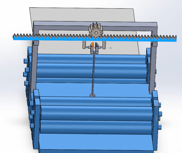
The roller-supported feed path guides material through the machine beneath the sealing head. Feeding and stamping need to be coordinated so the material reaches the intended contact position before the stamp acts.
Important design considerations include roller spacing, alignment between the feed path and stamp head, linkage clearance, and access around the mechanism. These relationships are visible in the assembly views and form the main integration problem addressed by the design.
The project produced a SolidWorks assembly and a supplied mechanism demonstration. It developed my experience in turning a real operating task into a mechanical design, combining rollers, gear motion, a linkage, and a supporting frame.
The design illustrates how several relatively simple mechanisms can be arranged to perform a coordinated operation. The video below provides the accompanying demonstration.
An overview of the documented project scope.
Supplied SolidWorks views and mechanism demonstration accompany the public project overview.
KEEP EXPLORING
01A fabricated and flight-tested electric UAV using three tilting propulsion units for vertical lift and transition to wing-borne forward flight.
 02
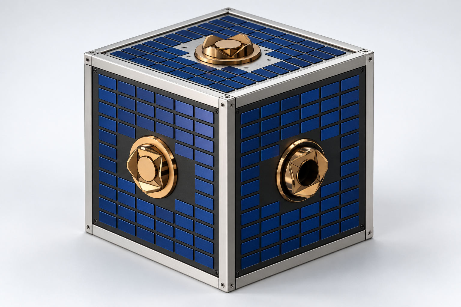
02A station-supported free-flying robot design for orbital inspection, positioning, assembly, and servicing, with nitrogen propulsion and six modular docking interfaces.
 03
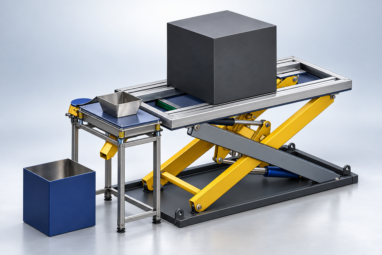
03Designed in SolidWorks for Michelin and developed into a siever prototype, combining mechanical fabrication, electrical motor wiring, and hands-on troubleshooting.