





 01
01SPACE SYSTEMSENGINEERING DESIGN V1.0
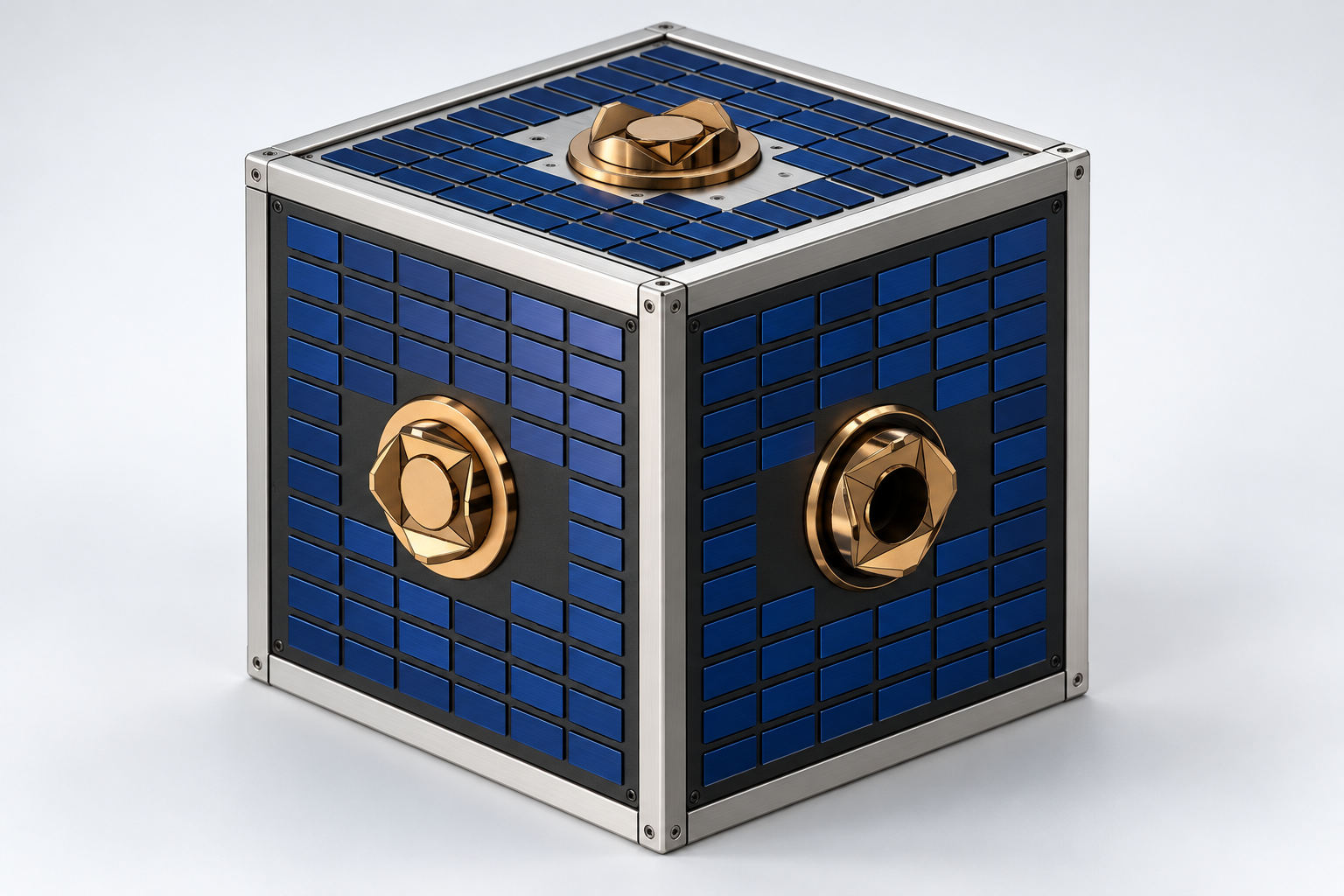
Spacebot v1.0 - Free-flying Robot
A station-supported free-flying robot design for orbital inspection, positioning, assembly, and servicing, with nitrogen propulsion and six modular docking interfaces.
AEROSPACE / VECTOR V1
A fabricated and flight-tested electric UAV using three tilting propulsion units for vertical lift and transition to wing-borne forward flight.
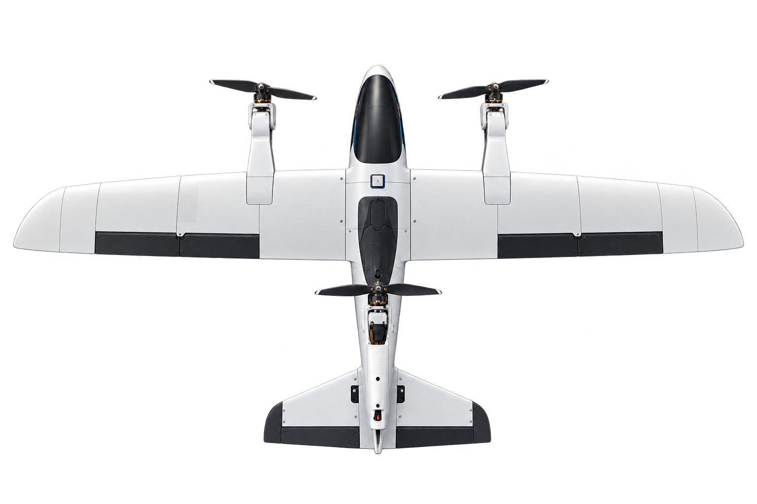
Vector V1 combines runway-independent vertical take-off with fixed-wing forward flight. Two electric motors sit on the wings and a third on the tail. Servo-driven mounts rotate the motor–propeller assemblies, allowing the same three propulsion units to support vertical lift and forward thrust.
Our team adapted the Falcon V2 airframe configuration with motor mounts, tilt mechanisms, avionics, and flight control. Development covered mechanical design, additive manufacturing, aerodynamic and dynamic analysis, electrical integration, controller tuning, and experimental flight trials.
Project overview · summary p. 1 ↗I designed the tail part and tilting mechanism, wired the UAV, worked with Mission Planner, and participated in flight testing. I also handled resource allocation and budgeting, developed the aims and objectives, and contributed the ArduPilot section of the report.
| Team member | Recorded contribution |
|---|---|
| Sudeera Perera | Tail and tilt-mechanism CAD; wiring; Mission Planner; flight testing; resources and budgeting; aims, objectives, and ArduPilot documentation. |
| N. K. Hewaarachchi | Conceptual design; airframe, ESC/controller mounts, stand and arm modelling; simulation; MATLAB state-space work; airframe assembly; literature review and time plan. |
| S. M. Lakmini | Airframe modelling and assembly; simulation and calculations; introduction and methodology. |
The project was completed at the University of Ruhuna under Dr. A. W. B. I. Annasiwaththa, with co-supervisor Ms. Anusara Wijerathna. The final report is dated 4 September 2026.
Final report · group contributions and project declaration ↗The wing and tail motor mounts create a shared propulsion architecture for both flight modes. In vertical lift, the motors provide the lifting force; during transition, the mounts tilt forward as airspeed builds and the wing progressively supports the aircraft.
Three concepts were compared using a weighted decision matrix covering mass, processing capability, power-to-weight ratio, mechanical reliability, energy storage, and manufacturing ease. The selected concept scored 8.65 out of 10. Fusion 360 and SolidWorks supported the airframe adaptation and mechanical interfaces.
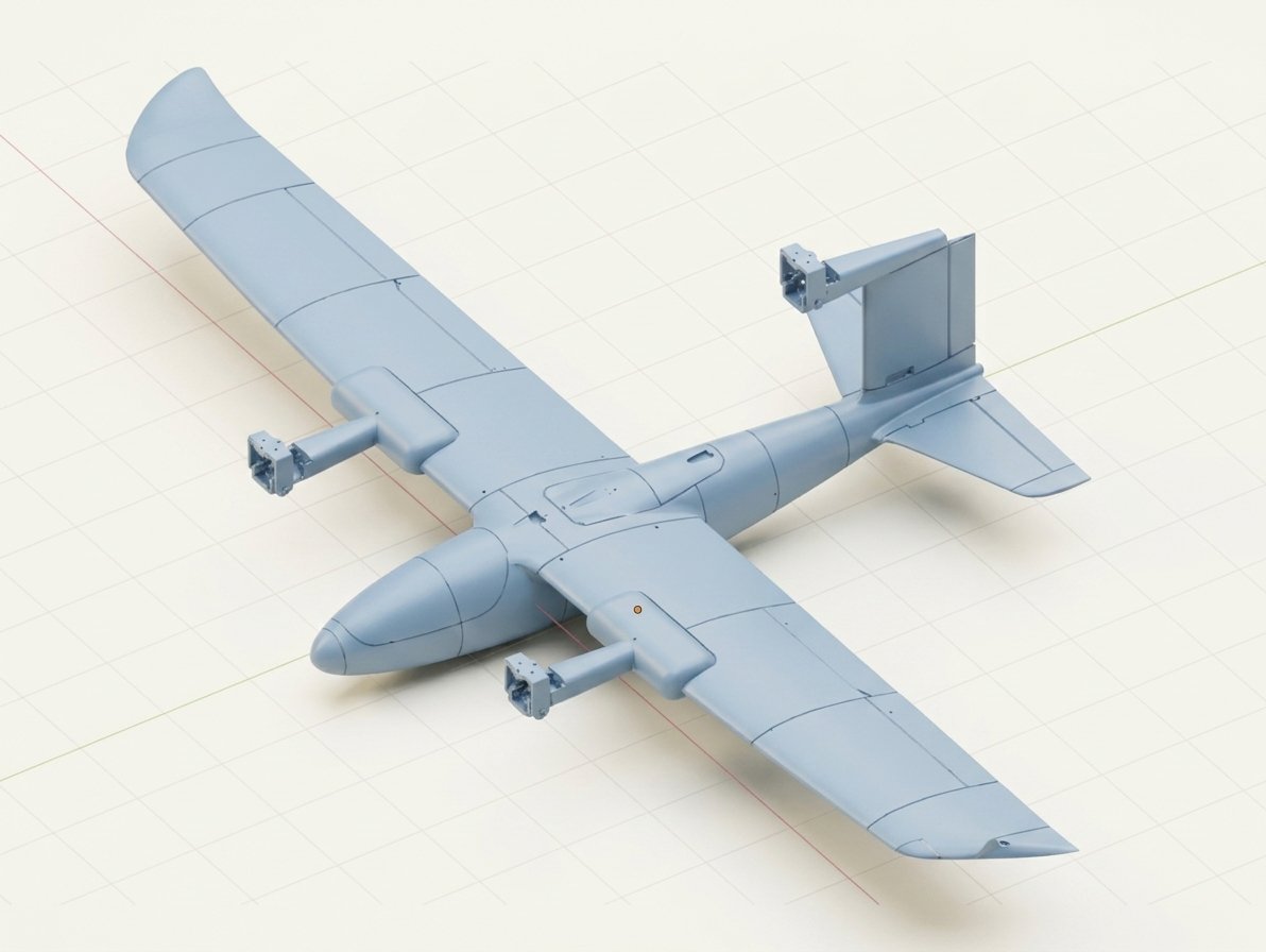
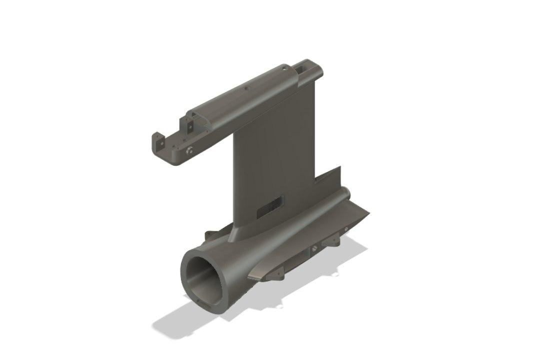
The airframe was fabricated by FDM 3D printing on a Creality K1 Max. LW-PLA formed the main aerodynamic sections, with PLA+ and PETG used for functional parts. Carbon-fibre and aluminium reinforcement tied the printed components into the structural assembly.
| Subsystem | Configuration |
|---|---|
| Propulsion | Three Hobbywing XRotor 2812, 1100 KV motors; Mamba F65 ESC. |
| Power system | 6S LiPo; nominal 22.2 V, as listed in the summary. |
| Flight control | Matek H743-WING; ArduPilot; ELRS receiver and GPS. |
| Tilt actuation | Emax ES3054 servos. |
| Control-surface actuation | ES08MAII servos. |
| Reported prototype mass | 2.75 kg in the summary configuration. |
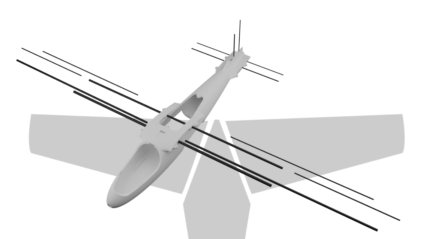
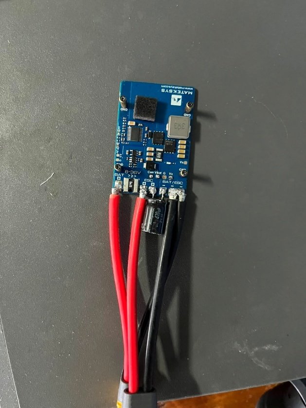
The table follows the supplied summary configuration. The full report includes other development and modelling assumptions, including a different battery description.
Prototype configuration · summary p. 2 ↗SolidWorks Flow Simulation examined airflow and pressure around the airframe, rotor downwash in hover, and propeller wakes in forward flight. XFLR5 aerodynamic data supported MATLAB state-space models for hover and cruise.
The 12-state modelling work covers translational velocities, angular rates, attitude, and position. Open-loop hover responses showed the need for active stabilization; the cruise response was more aerodynamically damped. These simulation results guided the control work and remain distinct from measured flight-log traces.
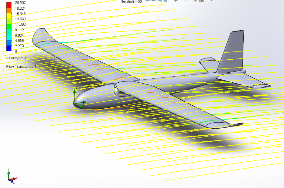
The prototype used ArduPilot's flight-control framework, configured through Mission Planner. Wiring and avionics integration connected the receiver, GPS, controller, motor drivers, tilt servos, and control surfaces.
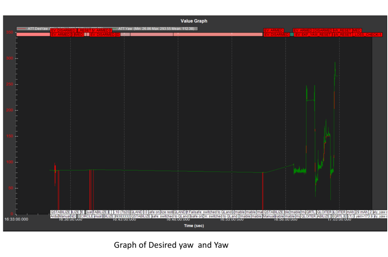
Initial testing identified roll and pitch oscillations, yaw response delay, altitude-holding problems, and transition disturbances. Flight-log review informed PID and feed-forward tuning, compass calibration, centre-of-gravity adjustments, and investigation of rear-motor heating.
The report describes a yaw diagnostic that separates delay in the commanded rate from delay in the measured response. This helps distinguish input shaping from controller tracking before changing gains.
Testing and refinement · summary p. 3 ↗ Final report · ArduPilot configuration and tuning ↗Testing progressed through ground levelling checks, VTOL hover trials, and horizontal-flight trials. Each flight mode was tested initially, then revisited after controller refinement.
The second VTOL test showed reduced roll and pitch oscillations and improved yaw tracking. The summary reports closer roll tracking in the second horizontal-flight test. The aircraft demonstrated vertical lift and transition into wing-borne forward flight.
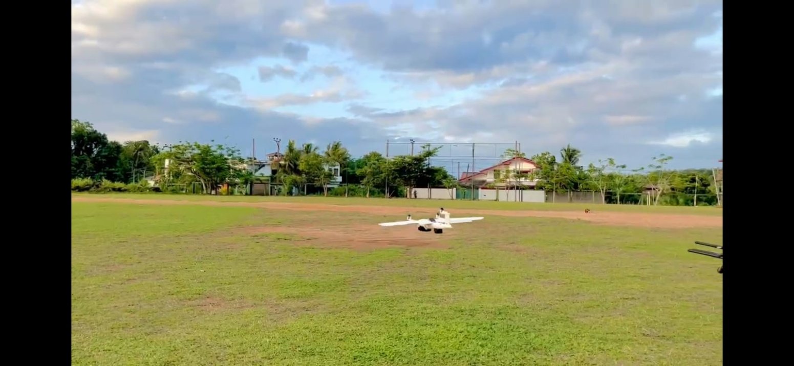
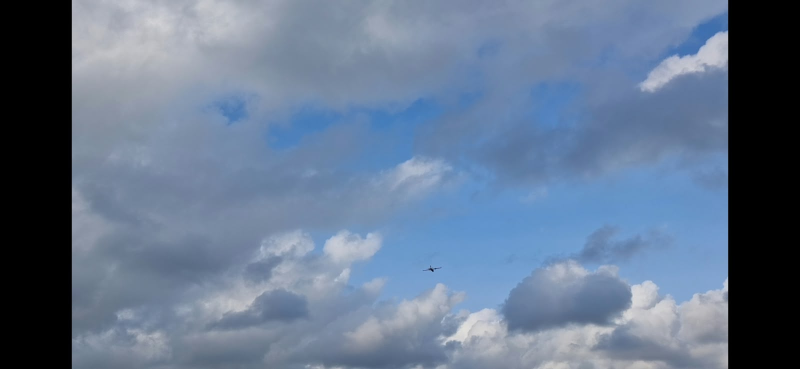
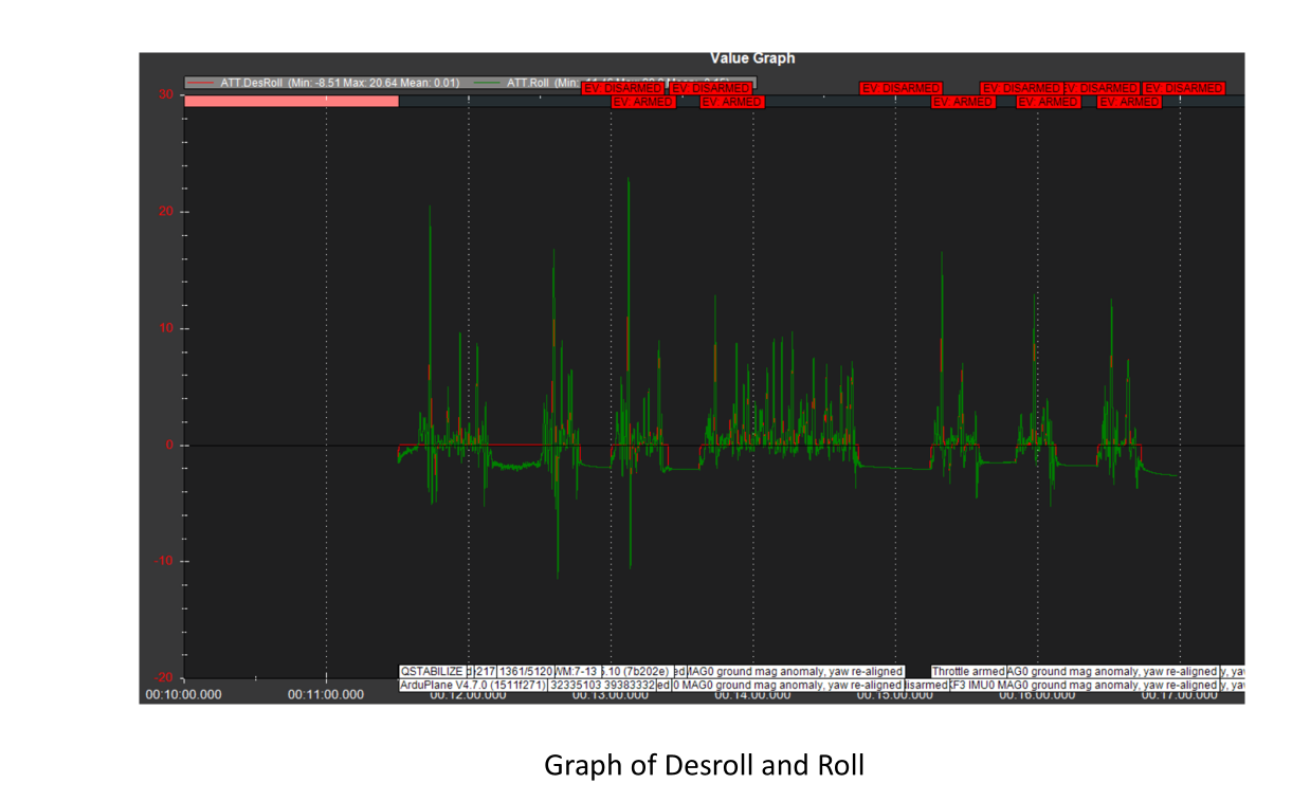
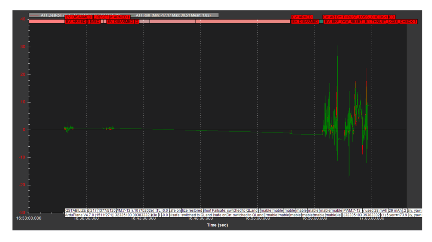
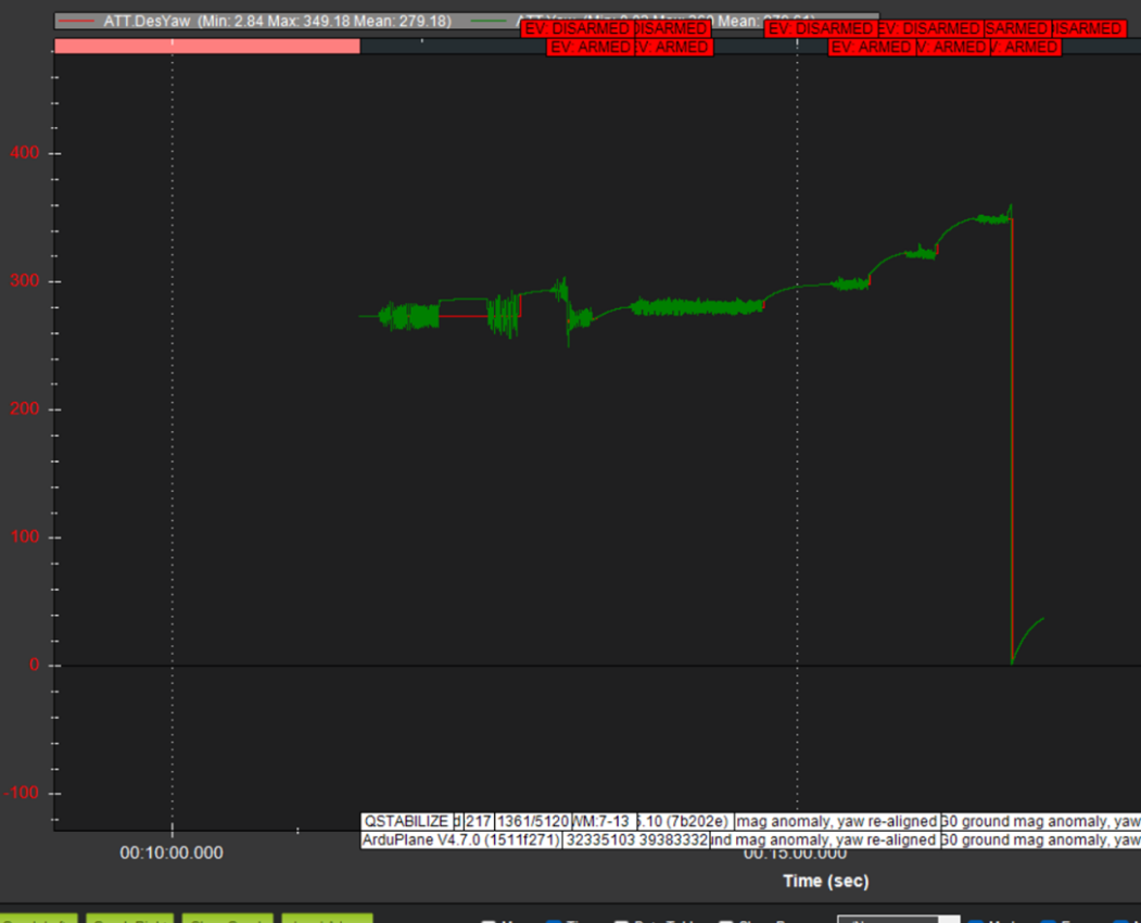
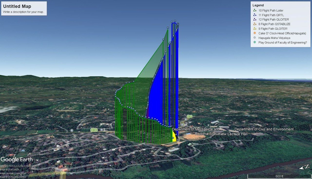
The prototype establishes vertical-lift and transition functionality. Longer-duration operations, payload use, and complete mission envelopes need dedicated testing.
| Item | Source value | Evidence status |
|---|---|---|
| Payload | 1 kg | Listed capability; mission-specific payload testing remains required. |
| Maximum cruise speed | 200 km/h | Listed specification, not a measured flight-test maximum. |
| Endurance | 90–120 minutes | Target dependent on battery and wind conditions; not demonstrated endurance. |
| Adaptive control and engine-failure recovery | Further development | Objectives beyond the demonstrated ArduPilot/PID flight trials. |
Further work includes repeated transition and landing trials, energy and endurance measurement, payload evaluation, adaptive control, and emergency recovery. Potential applications include inspection, environmental monitoring, search and rescue, and lightweight delivery to sites with restricted access.
Further development · summary p. 3 ↗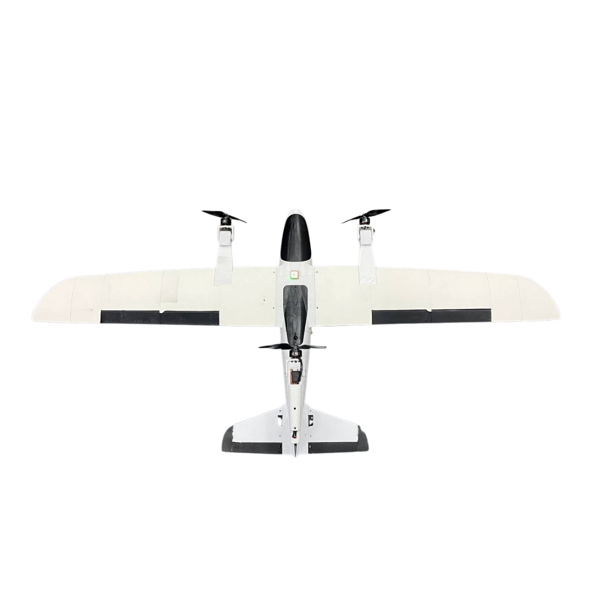
The project summary, final capstone report, original images, and demonstration video document the design and flight-testing work.
KEEP EXPLORING
01A station-supported free-flying robot design for orbital inspection, positioning, assembly, and servicing, with nitrogen propulsion and six modular docking interfaces.
 02
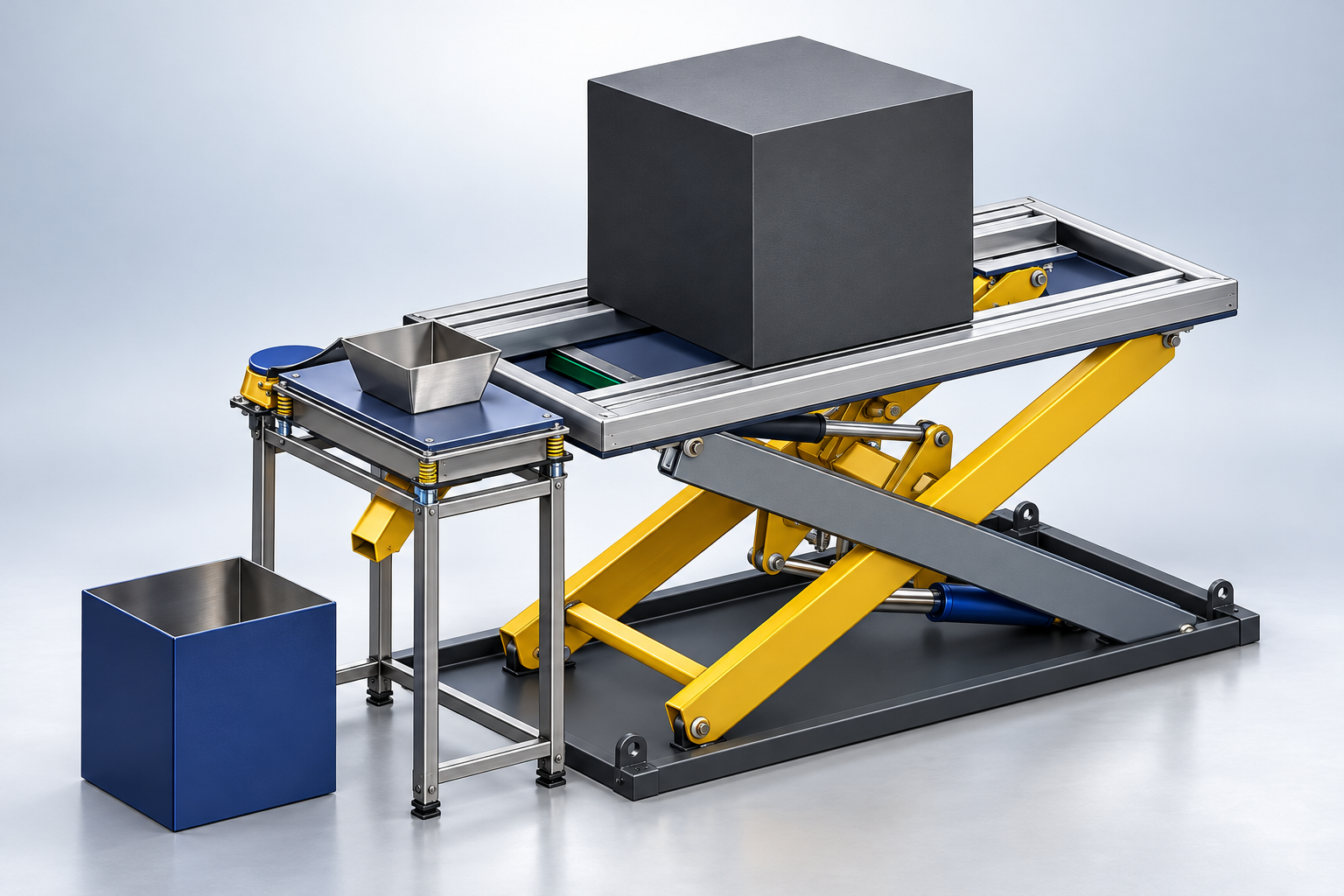
02Designed in SolidWorks for Michelin and developed into a siever prototype, combining mechanical fabrication, electrical motor wiring, and hands-on troubleshooting.
 03
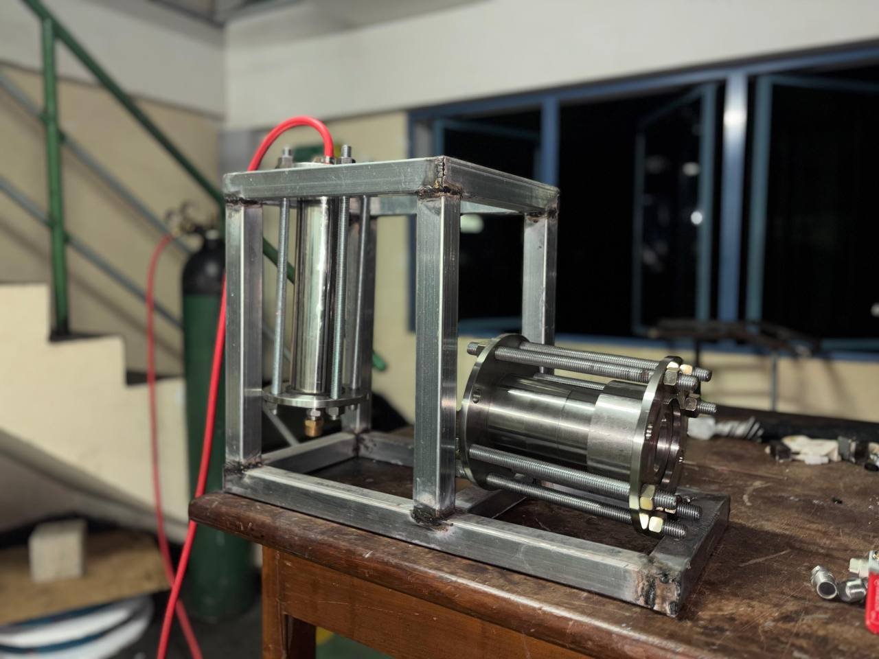
03Design and fabrication of a liquid-propellant model rocket engine, with experimental thrust analysis using gaseous oxygen and liquid kerosene at the University of Ruhuna.