 01
01AEROSPACEBUILT & FLIGHT-TESTED
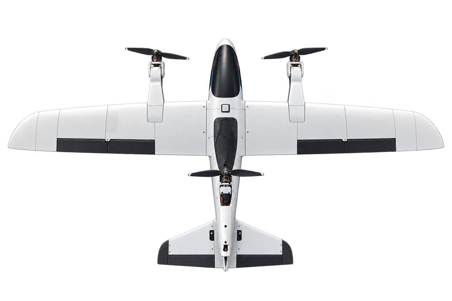
Vector V1 - Tri-rotor VTOL UAV
A fabricated and flight-tested electric UAV using three tilting propulsion units for vertical lift and transition to wing-borne forward flight.
SPACE SYSTEMS / SPACEBOT V1.0
A station-supported free-flying robot design for orbital inspection, positioning, assembly, and servicing, with nitrogen propulsion and six modular docking interfaces.
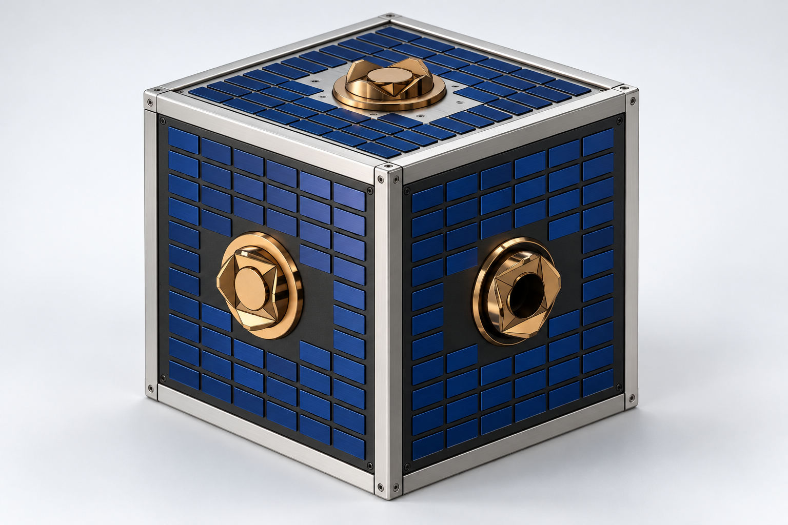
I developed Spacebot v1.0 as a reusable free-flying robotic platform for local inspection, component positioning, tool transfer, and anchored assembly or servicing in low Earth orbit. The October 2026 product document defines the mechanical configuration, subsystem interfaces, engineering budgets, and planned operation.
A dedicated station supplies recharging, nitrogen replenishment, and orbital transfers. The station matches the target orbit before releasing robots for local work; robots remain secured during station transfers. The operating region is 400–600 km LEO, with a nominal station altitude of approximately 500 km.
The project is an engineering design. The specifications, calculations, CAD, and animations define the intended system; they do not establish verified in-orbit performance.
Mission purpose and architecture · product document pp. 5–6 ↗The product document identifies me, S. R. Perera, as its author at the University of Ruhuna, under supervisor Mrs. M. S. D. Nimali. The design work connects the structural assembly, gas storage and propulsion, battery packaging, docking interfaces, and operational budgets.
The documented scope includes subsystem selection and packaging, preliminary performance calculations, mass and energy allocation, service interfaces, manufacturing considerations, operational states, and verification requirements. Flight software, fleet coordination, and service-station implementation require separate development.
Project authorship and supervision · product document p. 1 ↗| Parameter | Documented basis |
|---|---|
| Body | 500 × 500 × 500 mm core envelope. |
| Structure | Aluminium 7075-T73 members and reinforced removable panels. |
| Propulsion | 24 nitrogen cold-gas thrusters; three at each of eight corners. |
| Gas storage | 23.8 L COPV; approximately 360 mm outer diameter. |
| Docking | Six face-centred HOTDOCK-based interfaces. |
| Electrical storage | Four protected 8S3P battery packs; 96 cells. |
| Reference wet mass | 50 kg for sizing; final mass to be confirmed; tools and manipulators additional. |
| Attitude actuation | Cold-gas thrusters; no reaction wheels in the baseline. |
Tank supports, battery mounts, and docking hardpoints transfer loads into the primary frame. Removable panels provide access for battery removal, valve inspection, routing, and sensor alignment.
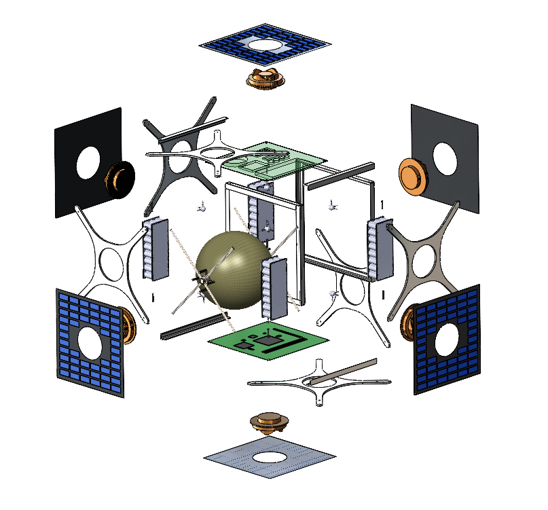
The design identifies a packaging constraint: a centred 360 mm tank in a 500 mm cube leaves 70 mm at each face centre, while the proposed pack depth is 80 mm. Offset placement or revised cell trays must close that clearance in CAD.
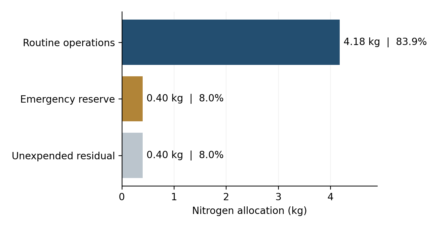
Design baseline · product document p. 7 ↗ Packaging and access · product document p. 10 ↗The gas circuit comprises a refill coupling, isolation valves, pressure vessel, pressure and temperature sensing, regulator, filter, manifold, and individually controlled nozzle branches. The design uses 1 N nominal thrust per jet, with an approximately 5 bar chamber-pressure sizing basis and 66 s specific impulse.
| Item | Design allowance |
|---|---|
| Fill basis | 200 bar absolute; calculation temperature 293 K. |
| Illustrative real-gas inventory | 4.976 kg using compressibility factor Z = 1.10. |
| Routine operations, including return | 4.18 kg. |
| Emergency reserve | 0.40 kg. |
| Unexpended residual | 0.40 kg. |
| Nozzle sizing basis | 1.30 mm throat; 2.10 mm exit; area ratio 2.61. |
At the 50 kg reference mass, ideal balanced four-jet translation provides 4 N and 0.080 m/s². Approximately 56.5 m/s routine equivalent velocity change is a calculated ideal budget, with attitude control, braking, geometry, and plume constraints reducing useful translation.
Propulsion and inventory · product document pp. 13–15 ↗ Ideal performance calculations · product document p. 24 ↗Four independently protected 8S3P packs supply a common bus. Each pack has 24 reference cells; together the installation has 96 cells. Pack isolation, monitoring, balancing, precharge, and reverse-current protection support fault containment and controlled connection.
| Quantity | Planning value |
|---|---|
| Nominal bus voltage | 28.8 V. |
| Charge ceiling | 32.8 V. |
| Nameplate energy | 1536 Wh, using 16 Wh per reference cell. |
| Installed battery allocation | Approximately 17 kg. |
| Routine delivered energy | 663.55 Wh after planning reductions. |
| Protected recovery energy | 221.18 Wh after capacity, discharge, and conversion allowances. |
| Sortie duration target | 6–8 hours for a low-duty mixed mission. |
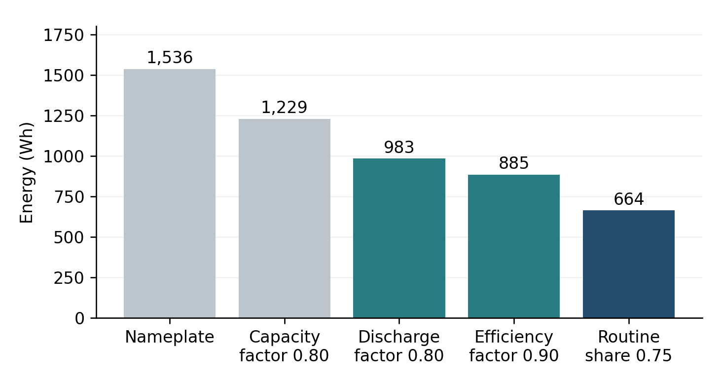
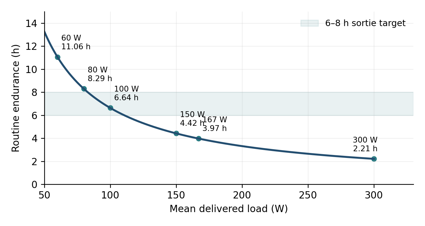
The 6–8 hour target requires an average delivered load of roughly 111–83 W. These are planning calculations; thermal conditions, battery behaviour, and feasible return trajectories also constrain a sortie.
Battery architecture · product document pp. 16–19 ↗Six face docking positions support attachment, tool exchange, power, and data. Docking loads pass through reinforced hardpoints. A separately qualified nitrogen service coupling handles refilling.
Navigation combines IMU, camera, ranging, and inertial attitude sensing. Relative sensing establishes target pose and closing motion; the star tracker supplies an inertial attitude reference. The propulsion allocation uses a 6 × 24 matrix of nozzle force vectors and their moments about the current centre of mass.
The document sets a provisional 0.05 m/s final-contact speed and requires latch confirmation before enabling services or tool loads. Plume direction, sensor visibility, failure cases, and retreat paths constrain approach and actuation.
Candidate electronics include Xiphos Q7S, ADIS16495, ST-16RT2, and other navigation and communications references. Their power, environmental suitability, interfaces, and qualification remain integration work.
Docking and candidate electronics · product document pp. 20–22 ↗The product document gives an energy-planning example built around intermittent anchored work. It uses 635 Wh over eight hours, leaving about 28.6 Wh of routine headroom and a separate recovery allowance.
| Phase | Time | Mean load | Energy |
|---|---|---|---|
| Deployment and checks | 0.5 h | 100 W | 50 Wh |
| Outbound approach | 1.0 h | 100 W | 100 Wh |
| Anchored intermittent work | 4.0 h | 75 W | 300 Wh |
| Inspection and repositioning | 1.5 h | 70 W | 105 Wh |
| Return and docking | 0.5 h | 100 W | 50 Wh |
| Contingency | 0.5 h | 60 W | 30 Wh |
| Total | 8.0 h | 79.4 W average | 635 Wh |
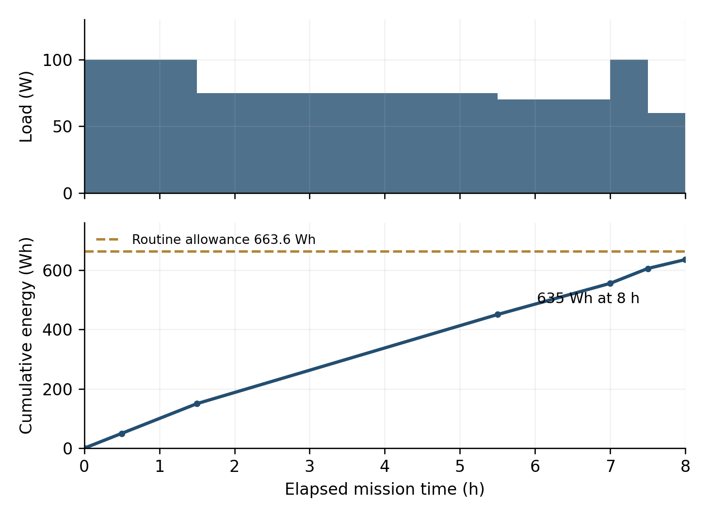
This is a calculated mission example. Continuous high-power tools shorten endurance; gas use, thermal feasibility, and the reserved return path require separate checks.
Eight-hour planning example · product document p. 25 ↗The thermal design considers internal dissipation, sunlight, Earth infrared, albedo, radiators, conductive spreaders, and multilayer insulation. The document's ideal radiator estimate excludes external heating and is not a final area selection.
The proposed assembly sequence integrates the frame and hardpoints, pressure hardware, batteries, docking fittings, avionics, thermal paths, and harnesses before panel closure. It then checks routing, nozzle alignment, sensor views, access, and mass properties.
After station capture, latch verification and thrust inhibition precede charging and gas servicing. Charging depends on battery temperature and health; refuelling requires pressure, temperature, leak, and inventory checks before release.
Thermal analysis · product document p. 26 ↗ Manufacturing and operation · product document pp. 27–29 ↗Spacebot v1.0 establishes the system architecture, CAD arrangement, and preliminary engineering budgets. Final mass and inertia, pressure-vessel qualification, nozzle performance, battery packaging, interface loads, thermal behaviour, and control authority still require verification.
Verification priorities include docking and latch demonstrations, battery isolation, fault injection, leak and service-interface tests, thrust allocation with plume restrictions, mission-return simulation, and structural retention testing. The document treats manipulators and mission tools as additional modules outside the reference wet-mass sizing.
The supplied videos illustrate the intended operation sequence. They are design animations rather than evidence of a built or flown orbital system.
Functional verification requirements · product document p. 8 ↗ Configuration summary · product document p. 30 ↗An overview of the documented project scope.
The October 2026 product document defines the Spacebot v1.0 baseline. The supplied CAD views and operation animations illustrate the design.
KEEP EXPLORING
01A fabricated and flight-tested electric UAV using three tilting propulsion units for vertical lift and transition to wing-borne forward flight.
 02
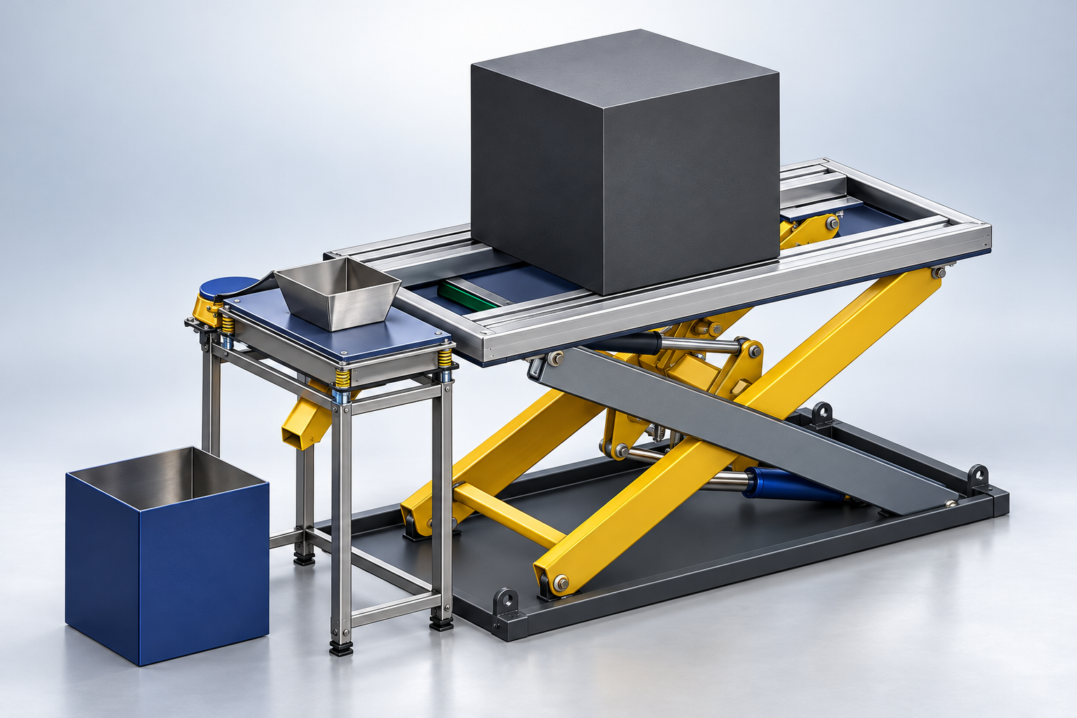
02Designed in SolidWorks for Michelin and developed into a siever prototype, combining mechanical fabrication, electrical motor wiring, and hands-on troubleshooting.
 03
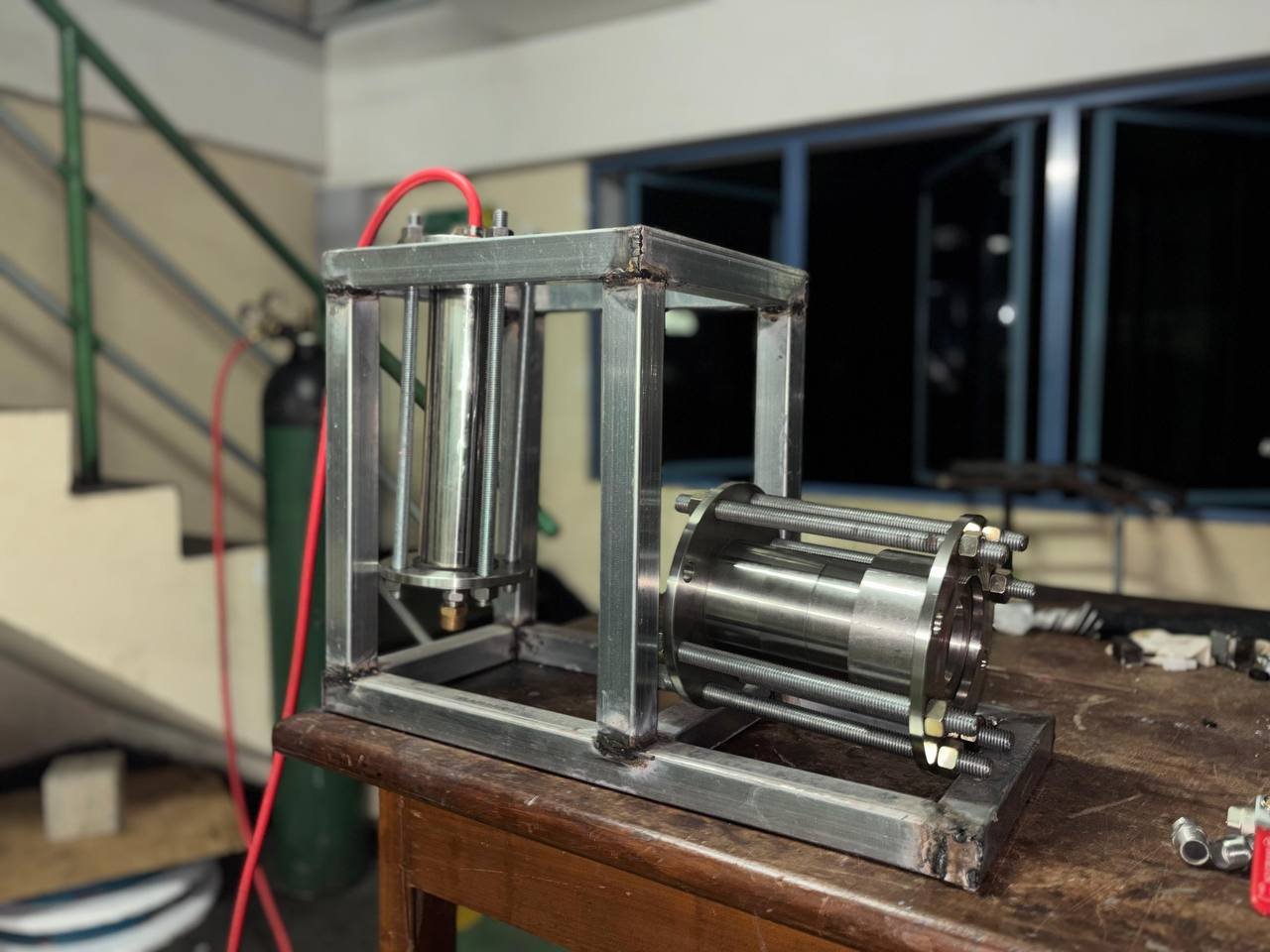
03Design and fabrication of a liquid-propellant model rocket engine, with experimental thrust analysis using gaseous oxygen and liquid kerosene at the University of Ruhuna.