 01
01AEROSPACEBUILT & FLIGHT-TESTED
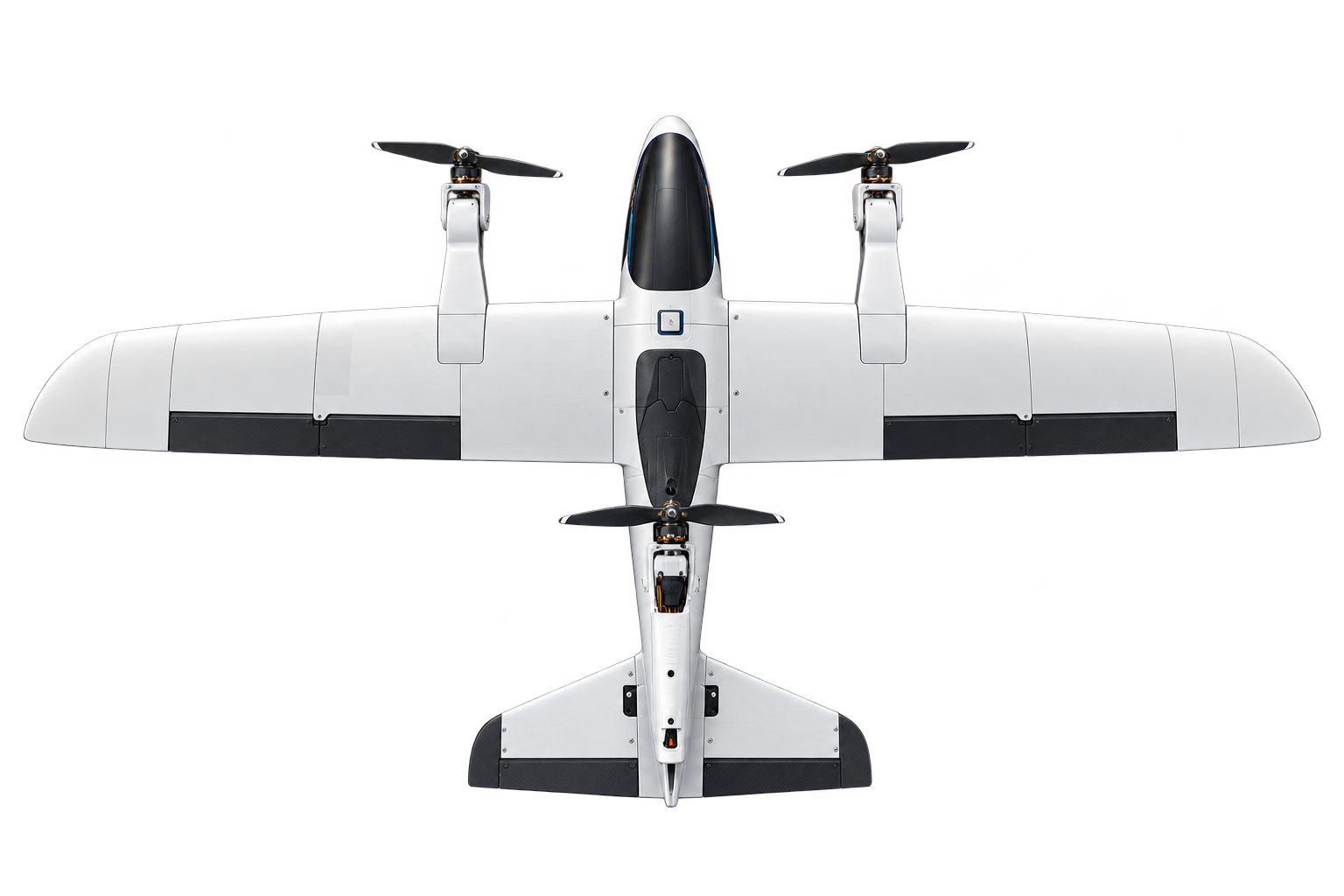
Vector V1 - Tri-rotor VTOL UAV
A fabricated and flight-tested electric UAV using three tilting propulsion units for vertical lift and transition to wing-borne forward flight.
MECHATRONICS / SMART HOME
A differential door-lock design that uses outside locking to trigger shutdown of nonessential household loads.
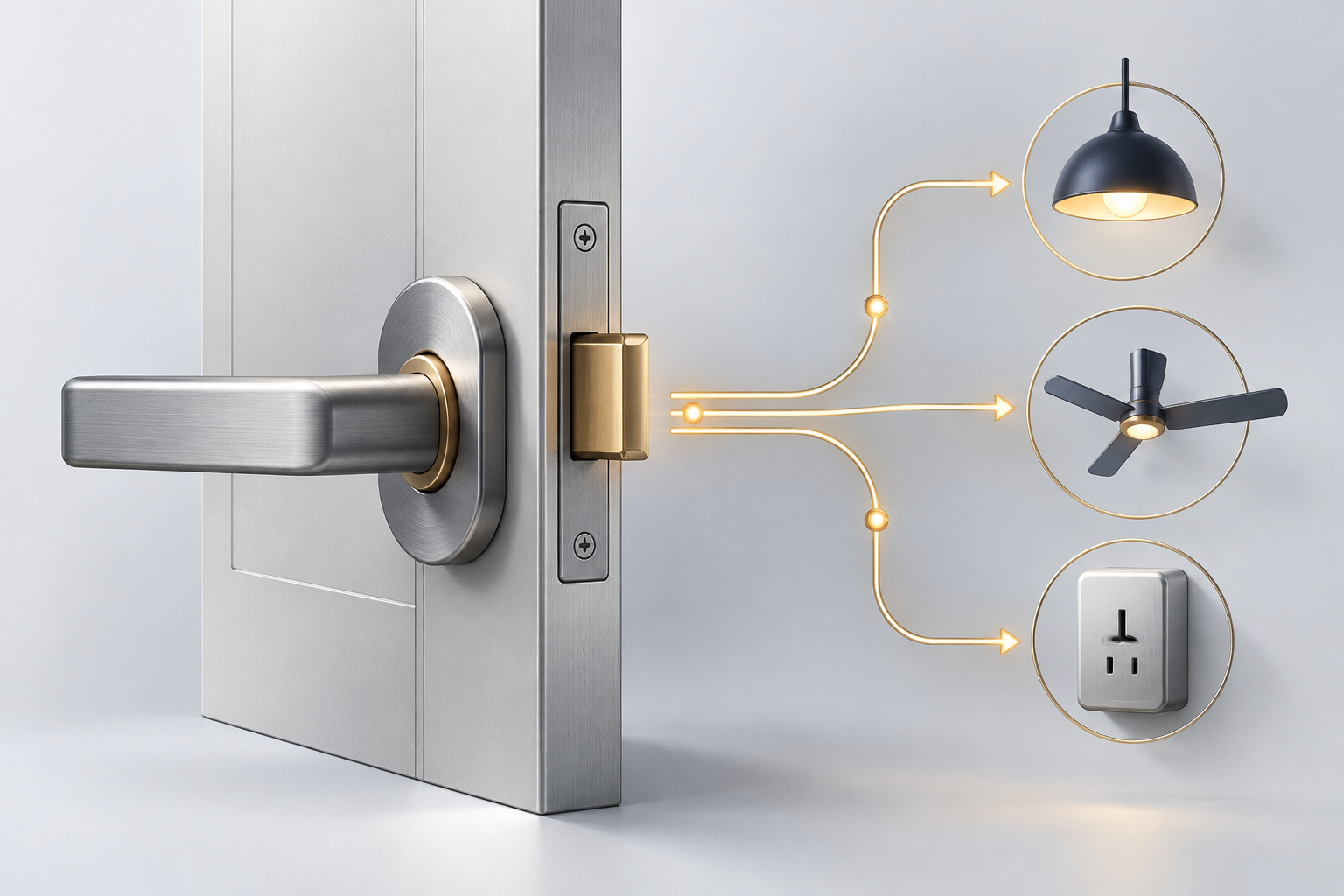
Group 17 developed the Home Power Saving Door Lock System for ME 3201: Engineering Design Methodology at the University of Ruhuna’s Department of Mechanical and Manufacturing Engineering.
The aim was to reduce electricity wasted by appliances left on when everyone leaves home. The design links a door-lock action to the power saving system so that nonessential loads can be switched off automatically.
The presentation lists N. A. A. Dhananjaya (EG/2021/4476), W. S. R. K. Perera (EG/2021/4717), H. S. D. Rodrigo (EG/2021/4763) and R. P. J. Rukshan (EG/2021/4766). It documents a group design effort without allocating individual subsystem responsibilities.
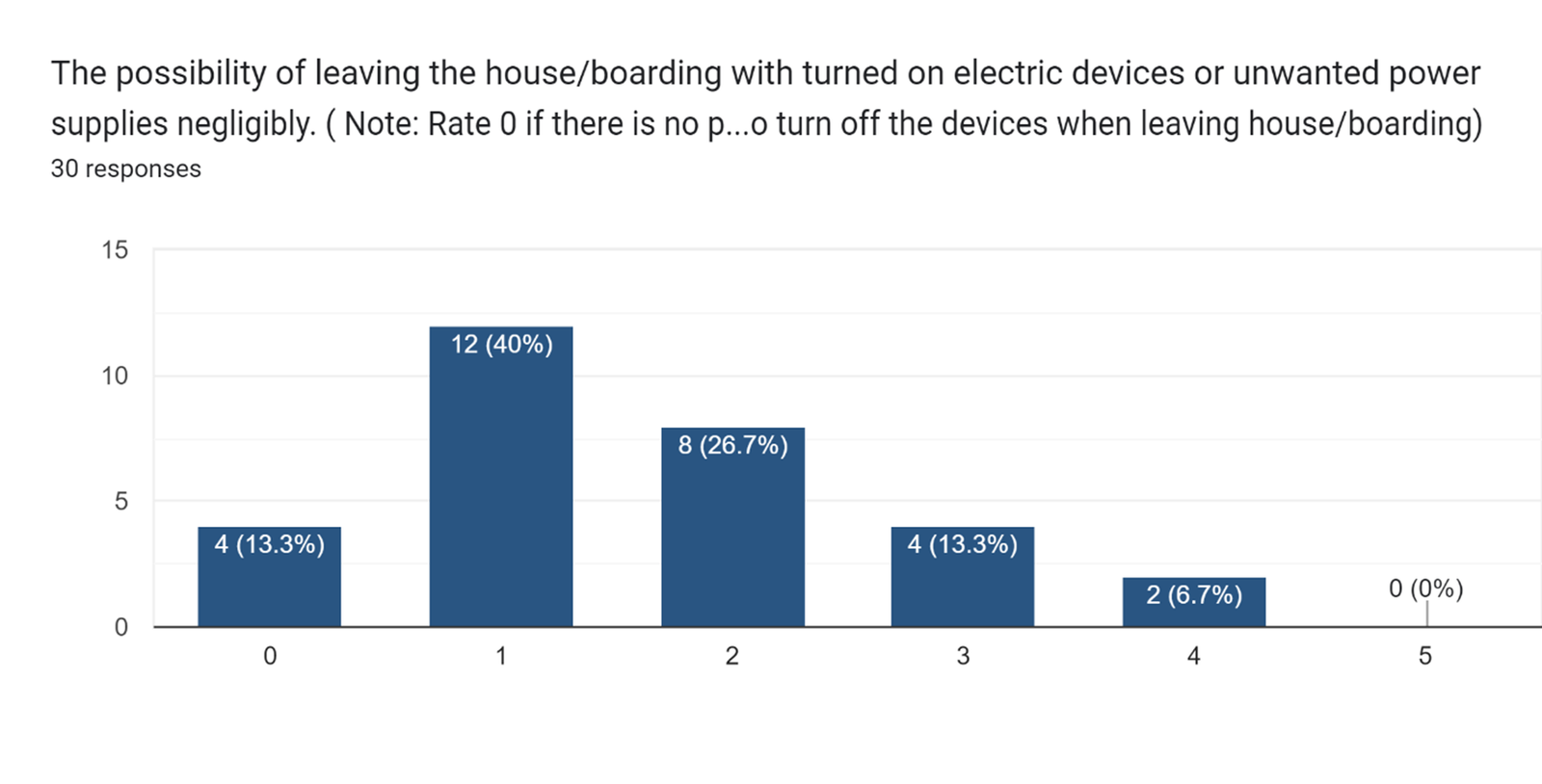
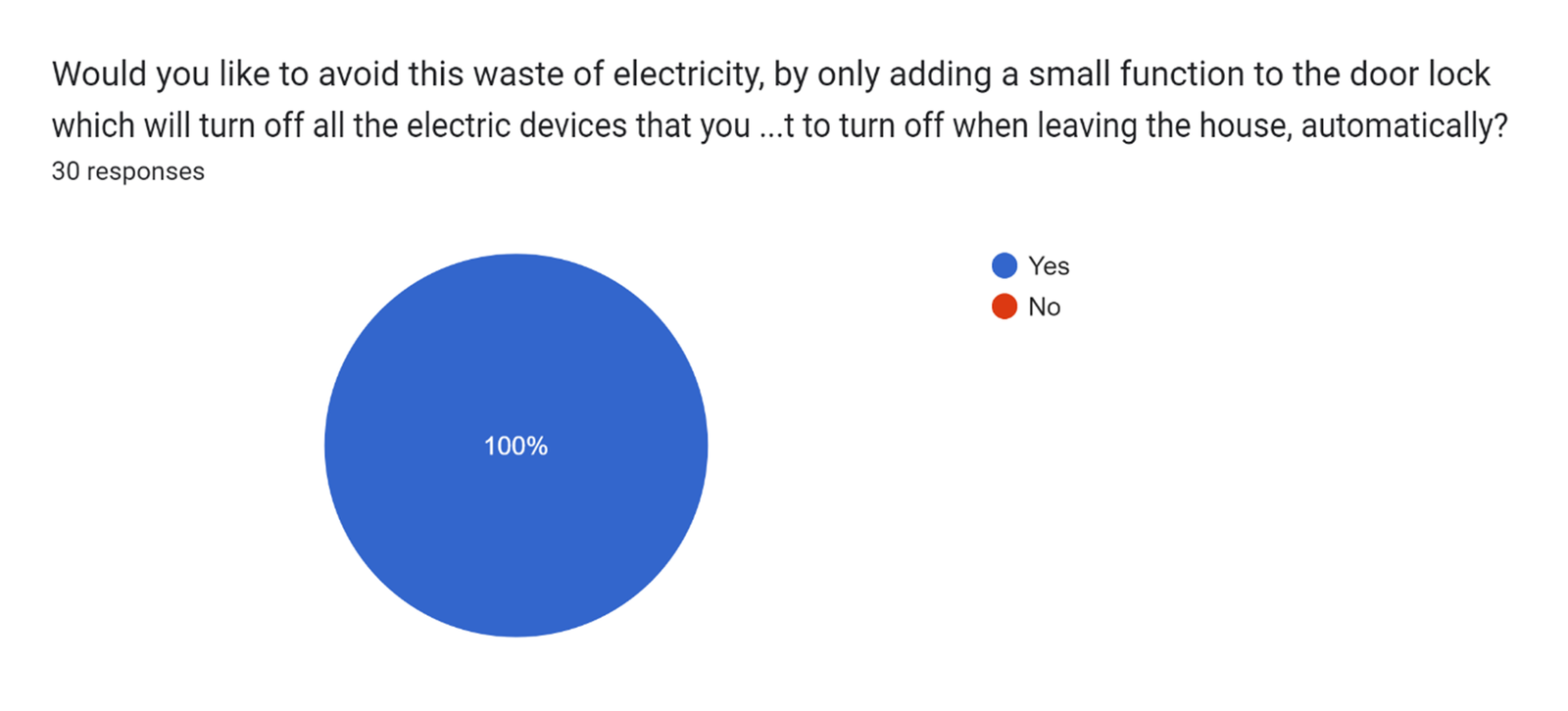
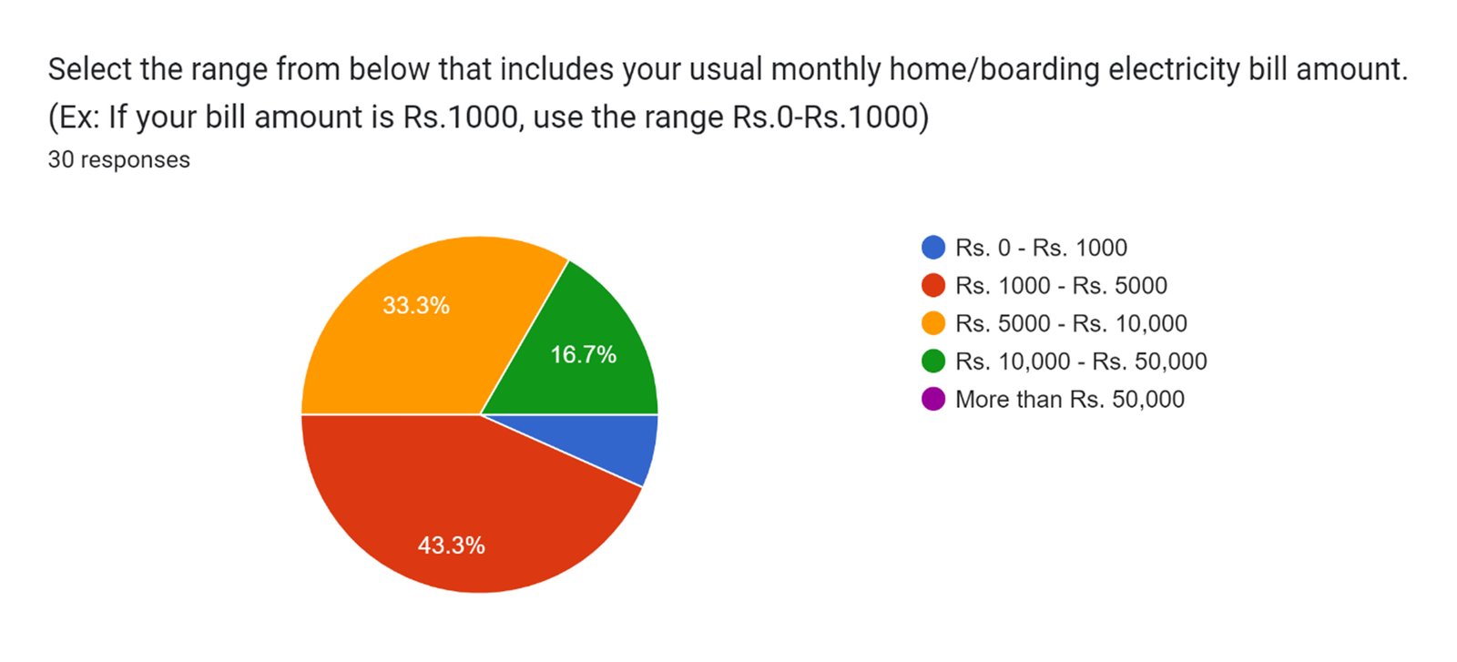
Design presentation · PDF page 1The team surveyed university students about electricity costs, forgetting powered devices when leaving home, and interest in an automatic solution. Each displayed chart records 30 responses.
The largest electricity-bill group, 43.3%, selected Rs. 1,000–5,000 per month; 33.3% selected Rs. 5,000–10,000. On the question about leaving devices powered, 26 of 30 respondents gave a nonzero rating on the 0–5 scale. All 30 expressed interest in the proposed door-lock addition.
These responses informed the design brief. They describe this student sample’s preferences and habits, rather than measured savings from the system.
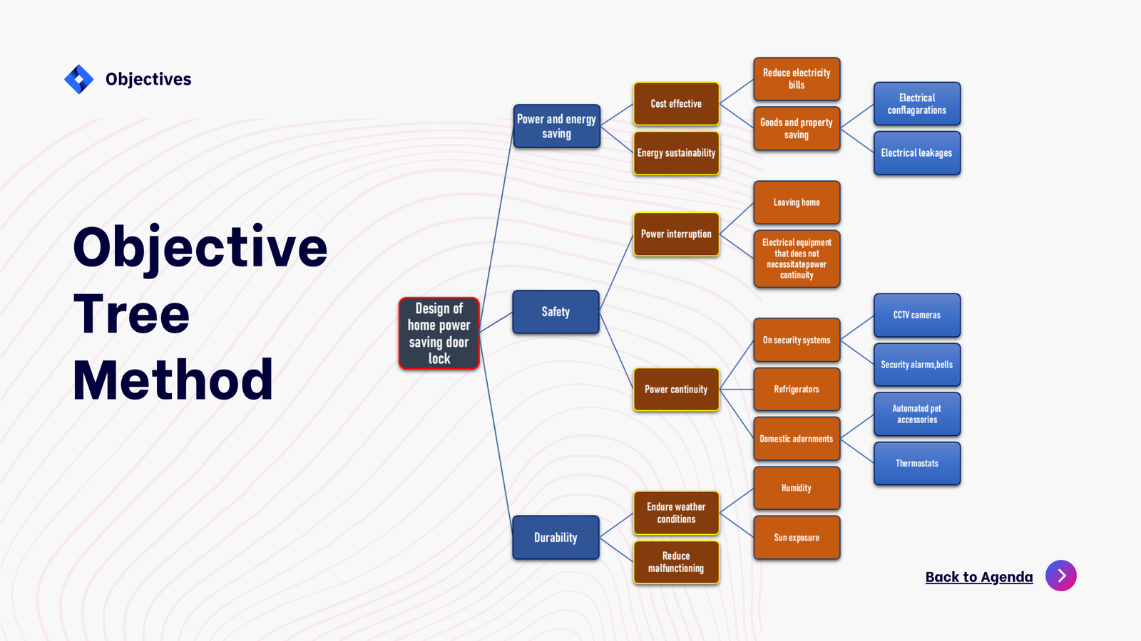
The objective tree groups requirements around power and energy saving, safety and durability. It calls for interrupting loads that do not need continuous power while maintaining supply to refrigerators, CCTV, security alarms and other equipment that must remain active.
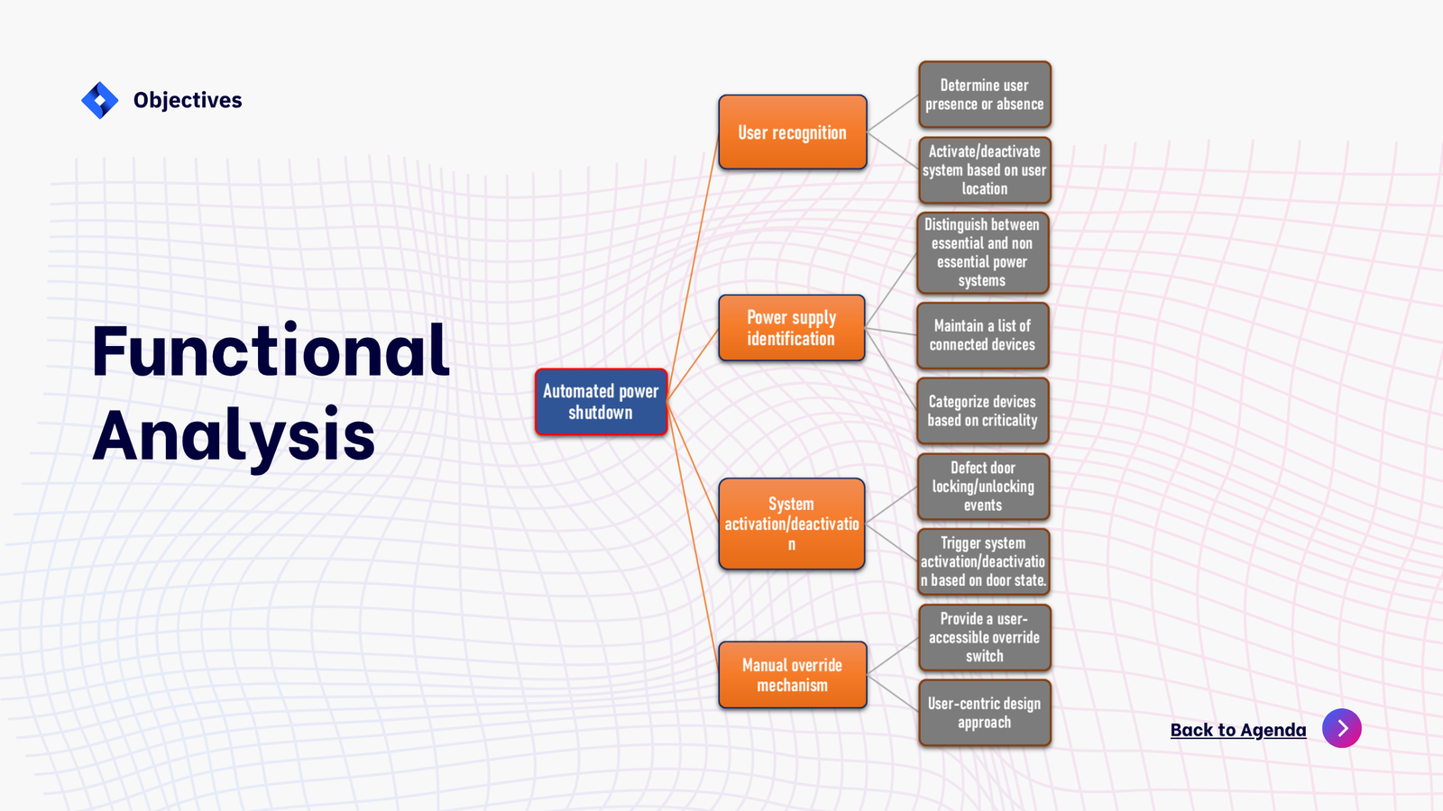
The functional analysis separates user-state recognition, identification of essential and nonessential loads, activation and deactivation from door-lock events, and a user-accessible manual override. These are design requirements; the presentation does not provide an installed switching circuit or test record.
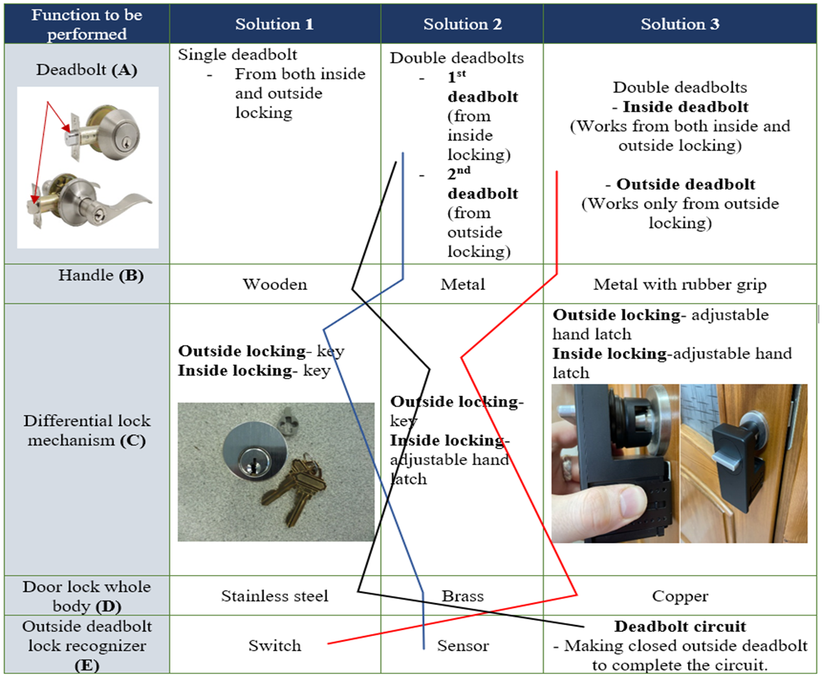
A morphological analysis compared alternatives for the deadbolt arrangement, handle, differential locking mechanism, body material and outside-lock recognition. Options included a shared deadbolt or separate deadbolts, key or adjustable hand-latch operation, stainless steel/brass/copper bodies, and a switch, sensor or deadbolt-completed circuit for recognition.
The team combined these alternatives into three candidate designs before comparing their weighted scores.
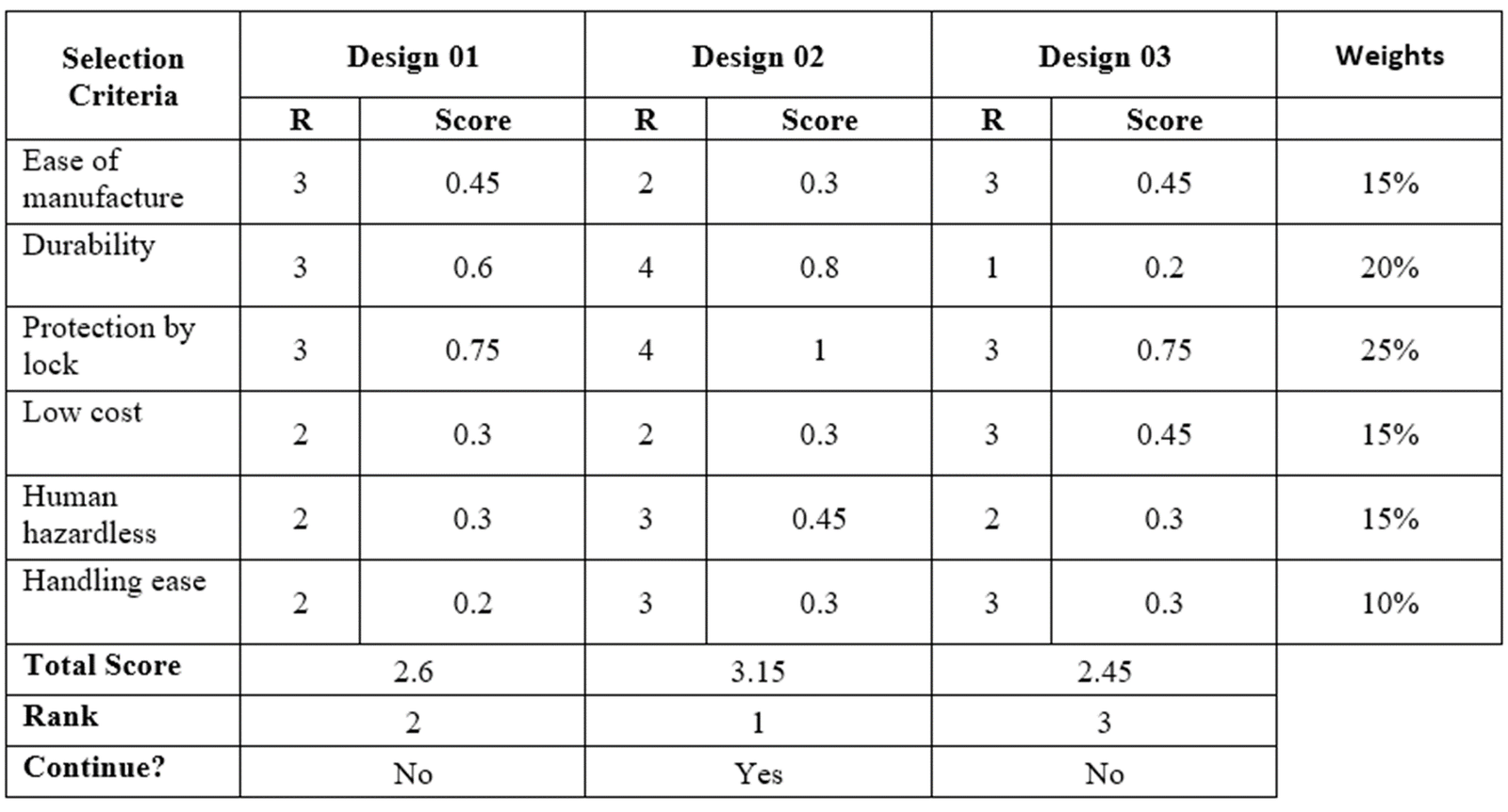
The decision matrix gave the greatest weights to protection by the lock (25%) and durability (20%). Ease of manufacture, low cost and user safety each received 15%; ease of handling received 10%.
Design 02 ranked first with a weighted score of 3.15, ahead of Design 01 at 2.60 and Design 03 at 2.45. The presentation selects Design 02 for further development.
The candidate combination shown for Design 02 is A3B3C2D3E1: separate deadbolts, a metal handle with a rubber grip, an outside key with an inside adjustable hand latch, a copper body, and switch recognition. These are the documented concept selections.
The proposed lock distinguishes locking from inside and outside through separate deadbolts. Locking from outside sends a signal to the power saving system to indicate that the household has left; the system can then disconnect the nonessential loads while preserving essential supply.
This approach uses the locking action as a proxy for occupancy. Its operating assumption is that outside locking means everyone has left. It does not independently count occupants or verify that the house is empty.
Design presentation · PDF page 14The study presents a survey-informed brief, functional requirements, three candidate concepts and a documented selection of a differential lock. The anticipated benefit is reduced waste from forgotten electrical loads.
The supplied PDF and PowerPoint contain the same 16-slide presentation. They do not include a detailed CAD assembly, fabricated prototype photographs, a switching schematic, or measured energy savings. The cover remains a labelled concept illustration; the original analysis figures and both source files are provided below.
Design presentation · PDF page 15Design presentation · PDF page 16An overview of the documented project scope.
The original PDF and editable PowerPoint are available above. Page citations throughout the design study point directly to the relevant PDF pages.
KEEP EXPLORING
01A fabricated and flight-tested electric UAV using three tilting propulsion units for vertical lift and transition to wing-borne forward flight.
 02
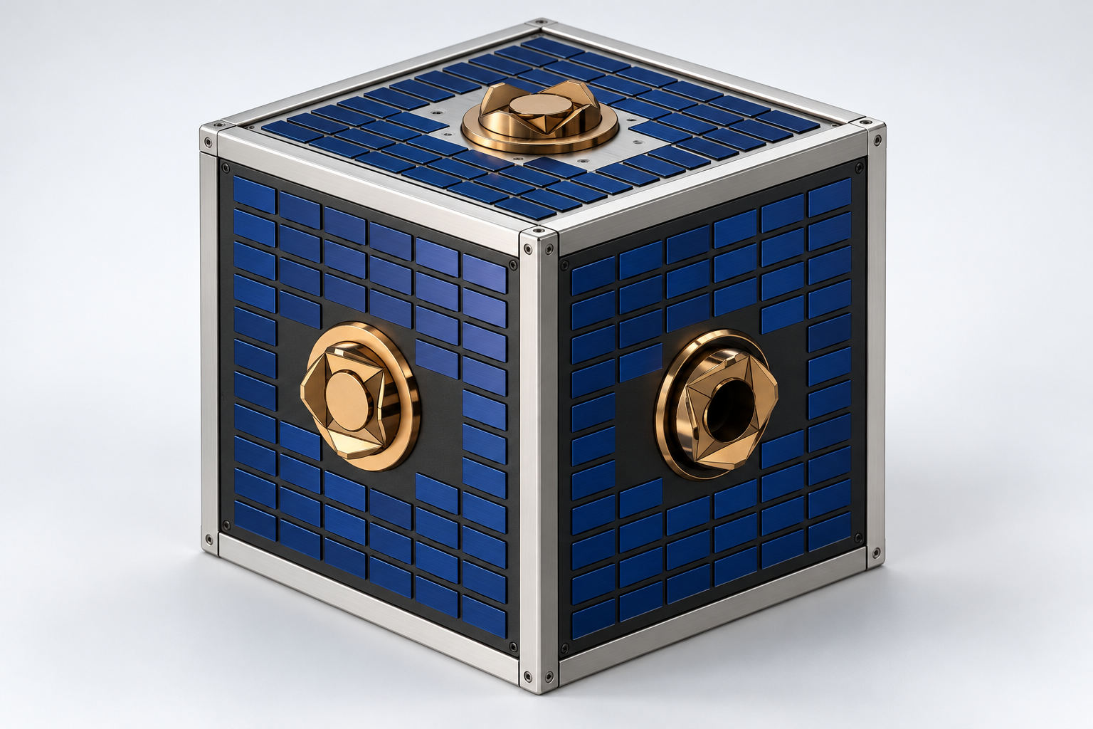
02A station-supported free-flying robot design for orbital inspection, positioning, assembly, and servicing, with nitrogen propulsion and six modular docking interfaces.
 03
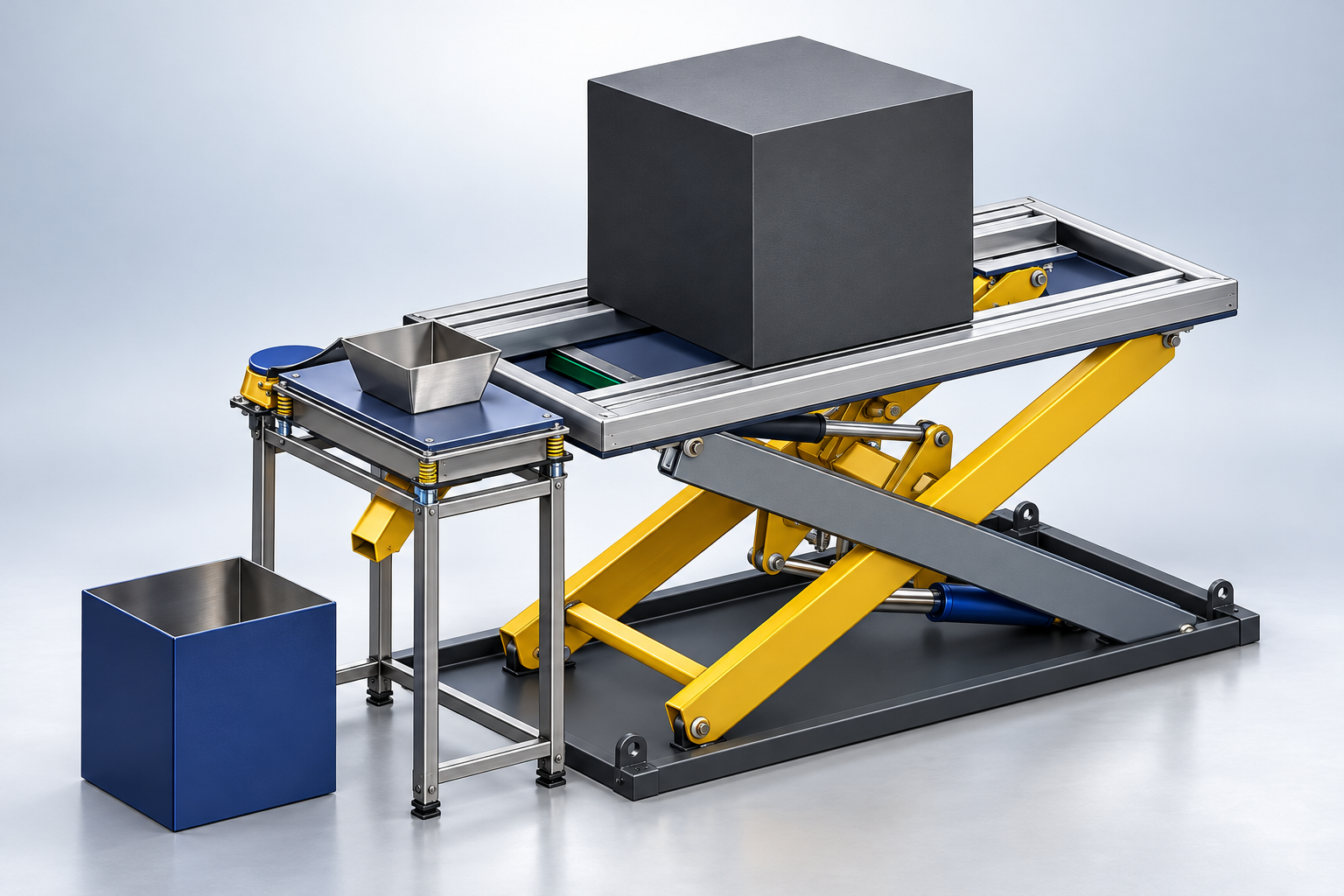
03Designed in SolidWorks for Michelin and developed into a siever prototype, combining mechanical fabrication, electrical motor wiring, and hands-on troubleshooting.